Mastering Civil 3D's Intersection Wizard to Create a 4-Way Intersection
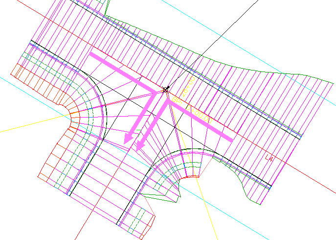
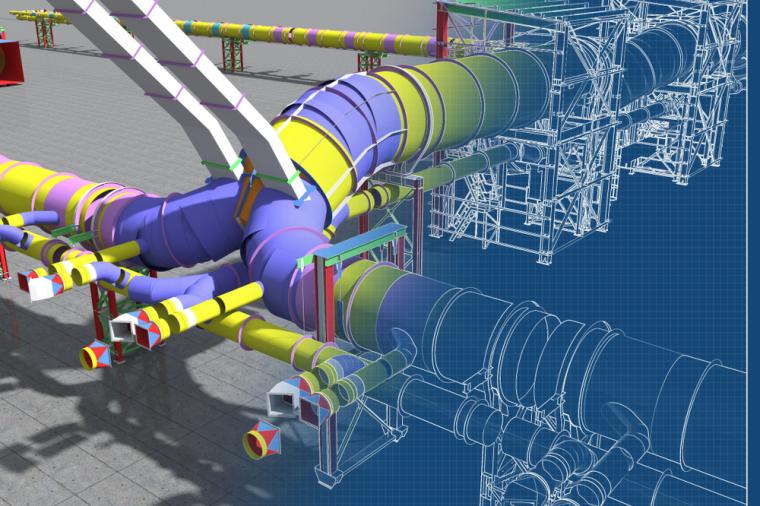
Civil 3D contains many engineering tools for roadway design. One of these tools is the Intersection wizard. The wizard walks the user step by step through the intersection design process and parametrically designs three or four way intersections. In addition to intersection design, the wizard defines widening for incoming, outgoing, or both lane types. This article describes the use of the intersection wizard to create a four way intersection that maintains each road’s crown elevation.
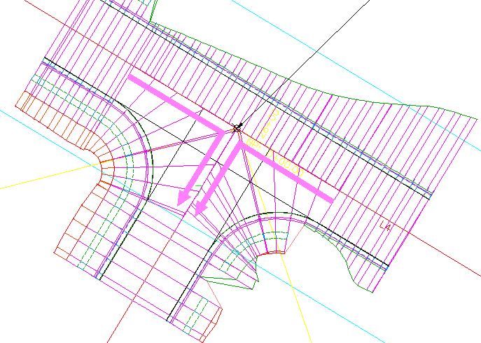
When creating the intersection assemblies, it is a challenge to determine what assembly configurations are needed to complete the intersection. The assembly configurations are determined by the type of intersection you are designing. When the intersection is a tee and holds the primary crown the intersection flattens the secondary road when it intersects the primary road. When creating this type of intersection, the primary road intersection assembly must have both roadway lanes. See the left side of Figure 1. When the intersection type maintains both primary and secondary crown, the primary intersection assembly contains only half of the primary road assembly. See the right side of Figure 1.
The reason for this difference is how the secondary road completes its portion of the intersection. To create an intersection that maintains both crowns, the primary road’s assembly contains a half section assembly and the curb assembly completes the intersection between the primary and secondary roads. See Figure 2.
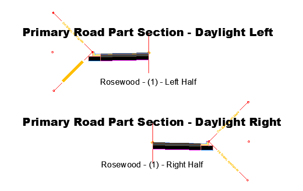
The primary road’s intersection assembly is either a half right or left daylight assembly. The assembly has only one lane to the right or left. See figure 3. The left half is for intersecting secondary roads from the right and the right half is for secondary roads intersecting from the left.
Assemblies – Primary Road
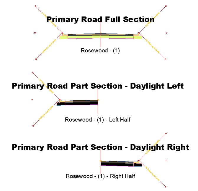
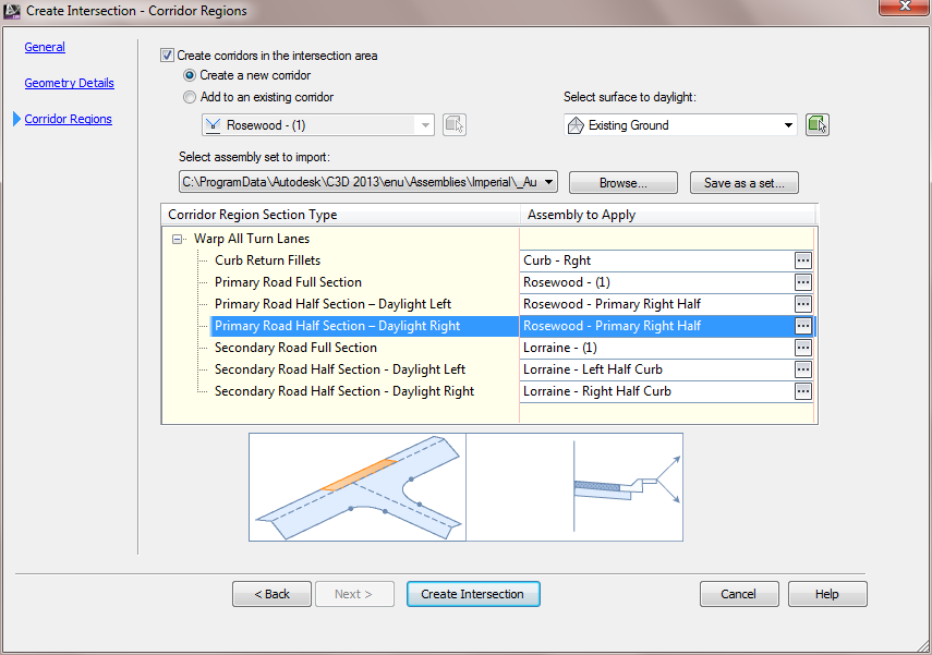
The assemblies for the primary road are found in Figure 4. When the intersection is a Tee and you hold both crowns, the Primary Road –Right and Left assemblies must contain a roadway’s half section. Both of these assemblies must be assigned to the intersection even though only one will be used.
The Primary Road Part Section – Daylight Right is for intersections where the secondary road intersects on the roadway’s left side. The Primary Road Part Section – Daylight Left is for intersections where the secondary road intersects on the roadway’s right side. Even though both sections are assigned in the wizard only one of the sections is used.
Assemblies – Secondary Road
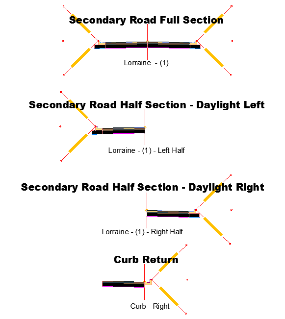
The secondary road assemblies are in Figure 5. The Secondary Road Half Section –Daylight Left and Right sections are used when there is a secondary road widening.
The last assembly in Figure 5 is the curb return assembly. The curb assembly follows a curb return alignment and creates the secondary’s portion of the intersection. The intersection creation process prefers the right curb assembly.
With a Tee Intersection with no widening, only the secondary road full section is used to create the intersection.
Intersection Assembly Assignment
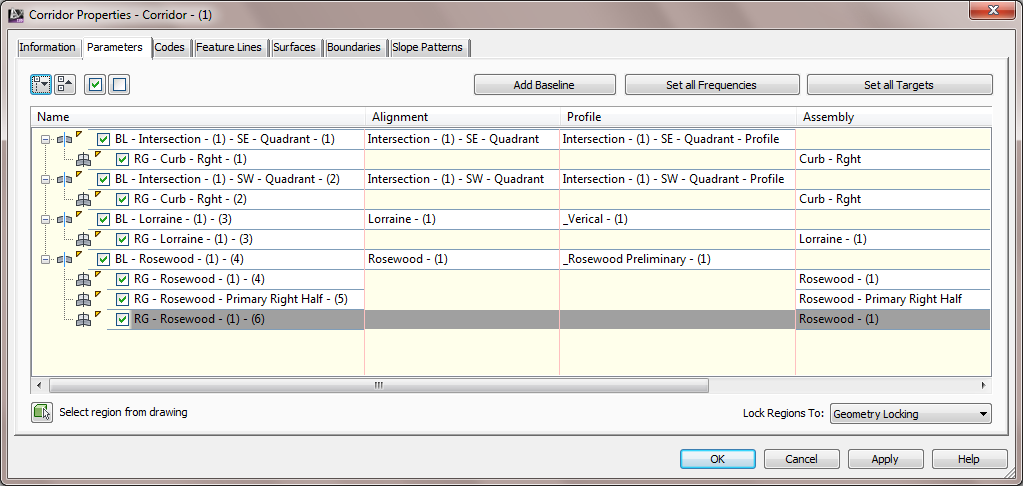
When creating the Tee Intersection, you must assign the correct assemblies. Figure 6 has the assembly assignments for a Tee Intersection that holds both crown elevations.
Corridor Properties – Tee Intersection Maintain Both Crowns
The resulting intersection from a Tee Intersection holding Corridor Properties – Tee Intersection Maintain Both Crowns the primary road’s crown with no widening uses the minimum number of assemblies. See Figure 7.
Happy intersection designing!
Written by Phillip Zimmerman, Senior Solutions Engineer, IMAGINiT Technologies.
This article was originally published on IMAGINiT’s Civil Solutions blog and was re-printed here with kind permission!
About the Author
Phillip has been with IMAGINiT since 2004 as a senior solutions engineer, providing valued support and training on Autodesk products in the civil and geospatial industry.

